Independent Dual Extruder 3D Printer Motherboard (Version 1) [Stop Production]
Independent Dual Extruder 3D Printer Motherboard (Version 1) [Stop Production]
Couldn't load pickup availability
This model has been discontinued and only 32-bit boards are available, order here
https://warm.fit/products/tenlog-dmp-7-axis-32-bit-motherboard-marlin-2-0-with-wi-fi-for-tl-d3-d5-d6
We have end A4988 Version, only TMC2208 Version is available.
Tenlog DMP 7-axis Motherboard with TMC2208 Driver, Work quieter and stable. This motherboard is pre-installed with 7pcs drivers, and with our newest Smart DMP 3D Printing Firmware.
The Version 1 and 2 Motherboard Use the Same Firmware
You Can Only Use the Same Motherboard as Your Current Host, the Wrong Version Will Lose the Warranty!
Tenlog DMP 7-axis motherboard contains seven TMC2208 drivers, Suitable for Hands 2, TL-D3 Pro, TL-D3S, TL-D5, TL-D6.
This kit comes with a touch screen and is equipped with a brand new UI.
Motherboard:
Input Voltage: 24V
Hot Bed Output Voltage: 24V
Support Power-loss Recover & Filament Runout Detection
SD Card Slot*1
USB Type-B Port*1
Tenlog 15Pin All-in-One Connector*2
Controllable Number of Motors: 7
Master Chip: Mega2560
Whether to Pre-install Firmware: Yes, with Newest Version
| Microcontroller | ATmega2560 |
| Operating Voltage | 5V |
| Input Voltage (recommended) | 7-12V |
| Input Voltage (limit) | 6-20V |
| Digital I/O Pins | 54 (of which 15 provide PWM output) |
| Analog Input Pins | 16 |
| DC Current per I/O Pin | 20 mA |
| DC Current for 3.3V Pin | 50 mA |
| Flash Memory | 256 KB of which 8 KB used by bootloader |
| SRAM | 8 KB |
| EEPROM | 4 KB |
| Clock Speed | 16 MHz |
| LED_BUILTIN | 13 |
| Length | 101.52 mm |
| Width | 53.3 mm |
Touch Screen:
4.3-inch 480*272 LCD Touch Screen for TL-D3 Pro, TL-D5, TL-D6 OR
3.5-inch 480*320 LCD Touch Screen for Hands 2
Whether to Pre-install Firmware: Yes, with Newest UI

How to Upgrade Drivers to TMC2208 from A4988
New method, no need to change pin of motor wire
watch video here
https://www.tenlog3d.com/blog/how-to-upgrade-a4988-to-tmc2208_b22
Old Method:
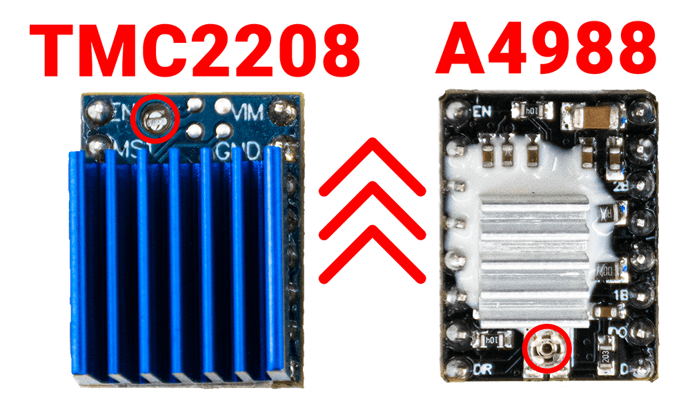
1. Please make sure that the drive module and motherboard are placed in the direction shown in the figure below. Please note the direction of the screws in the red circle⭕.

2. Change the wire sequence of the total 7 motors as shown in the figure below.

Share
![Independent Dual Extruder 3D Printer Motherboard (Version 1) [Stop Production]](http://warm.fit/cdn/shop/products/7-axisDMP3DPritnerwithTMC2208DriverChip_2039973d-53ab-4045-a431-f3da72d37a29.png?v=1649641394&width=1445)
![Independent Dual Extruder 3D Printer Motherboard (Version 1) [Stop Production]](http://warm.fit/cdn/shop/products/TMC2208MotherboardwithLCD_26af3ac1-ba56-4a57-9e9e-99a0bbab70f5.png?v=1649641394&width=1445)

